
Heat exchanger
To understand what a heat exchanger is and how it works, you first need to be familiar with the theory of heat transfer.
Heat transfer theory
The laws of physics drive thermal energy to move through a system until the temperatures reach equilibrium. Heat can be transferred in the following ways:
- Radiation. Thermal energy is transferred by electromagnetic radiation;
- Conduction. Heat is transferred through a solid material;
- Convection. Heat is transferred when one medium comes into contact with another. Convection can be:
-
- natural (free). The movement of the medium depends entirely on differences in its density and temperature, which even out during the heat transfer process;
- forced. The movement of the medium depends partly or entirely on an external influence on that medium, for example the operation of a pump circulating the fluid.
It is worth knowing that:
- because of the temperature difference, heat always flows from the warmer medium to the colder medium;
- for heat transfer to take place, there must be a temperature difference between the two media;
- the amount of heat given off by the hot medium equals the amount of heat absorbed by the cold medium, excluding external losses.
Heat transfer fluid
A heat transfer fluid is a working medium that carries heat from a hotter environment to a colder one. Heat transfer fluids are either liquid (water, oil, organic compounds, liquid metals, molten salts) or gaseous (air, water vapour, gases, combustion products). The state of aggregation of the fluid may or may not change. Heat transfer fluids are characterised by intensive heat transfer, a high boiling point, high thermal resistance and low chemical and corrosive activity. Of the liquid heat transfer fluids, water is the most commonly used. Its thermal conductivity is higher than that of gases, but it forms deposits and causes corrosion of heat exchangers.
Heat exchanger
A heat exchanger is a device in which heat is exchanged between two or more heat transfer fluids, or between a fluid and a solid surface. By design, heat exchangers can be coil, plate, tube-in-tube, block, shell-and-tube and other types, and by the direction of fluid flow they can be parallel-flow, counter-flow or cross-flow. By operating principle they are recuperative, regenerative, contact (mixing) and internal-heat-source types. In a recuperative heat exchanger, the heat of one fluid is used to change the temperature of another by convection. In regenerative heat exchangers, the heating and the heated fluids alternately flow over the same surfaces. In contact heat exchangers, heat is exchanged as both fluids touch (mix). In an internal-heat-source heat exchanger, the heat source is a chemical reaction or an electric heater inside the unit.
The most commonly used types of heat exchangers are:
- Plate heat exchangers: made of corrugated plates between which two fluids flow. Heat is transferred through the plate wall. Plate heat exchangers are compact and easy to clean;
- Tubular heat exchangers: made of tubes through which one fluid flows, while another fluid flows around the tubes. Heat is transferred through the tube wall. Tubular heat exchangers are robust and resistant to high pressure;
- Air heaters: used to heat air. Air heaters can be of various designs, for example plate, tubular and regenerative;
- Condensers and evaporators: used to condense vapours and evaporate liquids. Condensers and evaporators are often used in refrigeration systems.
In heat exchangers, heat is transferred until the temperatures equalise. The efficiency of heat transfer is determined by the thermal conductivity of the material, the wall thickness and the temperature difference between the fluids. It is important to note that fluids (gases) can be heated or cooled in heat exchangers even when the temperature difference is minimal.
Heat exchangers are used in a wide range of industries, for example in heating and cooling systems, the food industry, the chemical industry and the energy sector.
Plate heat exchanger
In many applications, the plate heat exchanger is considered the most efficient. The use of this type of heat exchanger usually means optimal heat transfer over a wide range of operating pressures and temperatures. It is also often the solution within the limits that the production equipment in use sets for these parameters.
The main advantages of the plate heat exchanger:
- Compact design. This type of heat exchanger needs much less space than a traditional shell-and-tube heat exchanger;
- The high turbulence of the medium flow creates good conditions for efficient heat transfer between the fluids, and the use of thin sheet metal in the heat transfer plates gives a higher heat transfer coefficient per unit of heat transfer surface area, resulting in a heat exchanger that is not only extremely compact but also efficient;
- Lower heat losses to the environment thanks to the small size of the heat exchanger.
- The high turbulence of the medium flow creates a self-cleaning effect. In addition, compared with a conventional shell-and-tube heat exchanger, the heat transfer surfaces of a plate heat exchanger are much less prone to fouling (deposit formation). This means that a plate heat exchanger can operate much longer between flushing cycles;
- Simple operation. A plate heat exchanger consists of a frame and a number of individual plates. By adding extra plates, the capacity of this type of heat exchanger is easy to increase. It is also easy to dismantle for cleaning (this applies to gasketed plate heat exchangers).
A plate heat exchanger has a variable thermal length. In many plate heat exchangers made by well-known manufacturers such as Alfa Laval, Hexonic, Kelvion, SWEP and others, plates with different pressing profiles are used. For example, if a plate with "H" channels is used, the heat exchanger has a higher pressure drop and operates more efficiently, because it has a long thermal channel and a longer heat transfer time. When an "L" plate is used, the heat exchanger works with a low pressure drop and, accordingly, a slightly lower heat transfer coefficient. Such a heat exchanger has a short thermal channel. A compromise between "H" and "L" (narrow and wide) channels, and between pressure drop and heat exchanger efficiency, can be achieved by using plates with different pressing patterns during assembly.
Applications of plate heat exchangers
The heat exchangers offered on the Amegata.lt supply platform can handle a variety of technological tasks. They can be used for both heating and cooling, air conditioning and cooling in various technological processes. They also ensure the sustainable use of surplus energy for secondary functions such as additional domestic hot water preparation and building heating or cooling.
Plate heat exchangers are most commonly used in the following industry sectors:
- District heating;
- District cooling;
- Heating of tap water;
- Heating the water of various pools (swimming pools, fish farming, etc.);
- Cooling of various engines;
- Cooling of various furnaces used in industry;
- The food, energy and chemical industries, where heating and/or cooling is required during the technological process;
- Solar heating systems.
In different processes, plate heat exchangers are used to cool hydraulic fluid, to cool various oils (for example engine oil), as an intermediate cooling unit for a heat pump, to cool air in ventilation systems, in solar heating systems, and so on.
The following types of heat transfer fluids are most commonly used in plate heat exchangers:
-
Water/water. Most of the heat exchangers we offer solve heat transfer tasks where the medium in both circuits is water (water/water mode). Solutions can vary:
-
Heating water. In this case, higher-temperature water is used, for example from a district heating system, a boiler or a domestic hot water pipe.
-
Cooling water. In this case, lower-temperature water is used, for example from a cooling tower, a river or the sea.
-
- Water/oil. In some industries, oil has to be cooled with water. This water can then be directed to a waste heat recovery system to recover the heat obtained from cooling the oil, which can then be used for various purposes.
- Water/glycol. Glycol is used to prevent the water from freezing. It is important to note that
the heat capacity of glycol differs from that of water, so heat exchangers with a larger heat transfer surface area are required. The physical properties of the various glycols are almost identical. Examples of glycols: ethylene glycol (mono-, di- or tri-), propylene glycol.
When working with synthetic oils, special gaskets are used. Plate heat exchangers can work with oil of viscosity up to 2,500 cP. In plate heat exchangers, an emulsion with a concentration below 5% can be used instead of water.
The range of plate heat exchangers is very wide. They can be extremely large units with a heat transfer surface area of up to 2,000 m² and a flow of 3,600 m³/h, or the smallest heat exchangers with a heat transfer surface of less than 1 m² and a flow of 0.18 m³/h.
Plate heat exchanger design
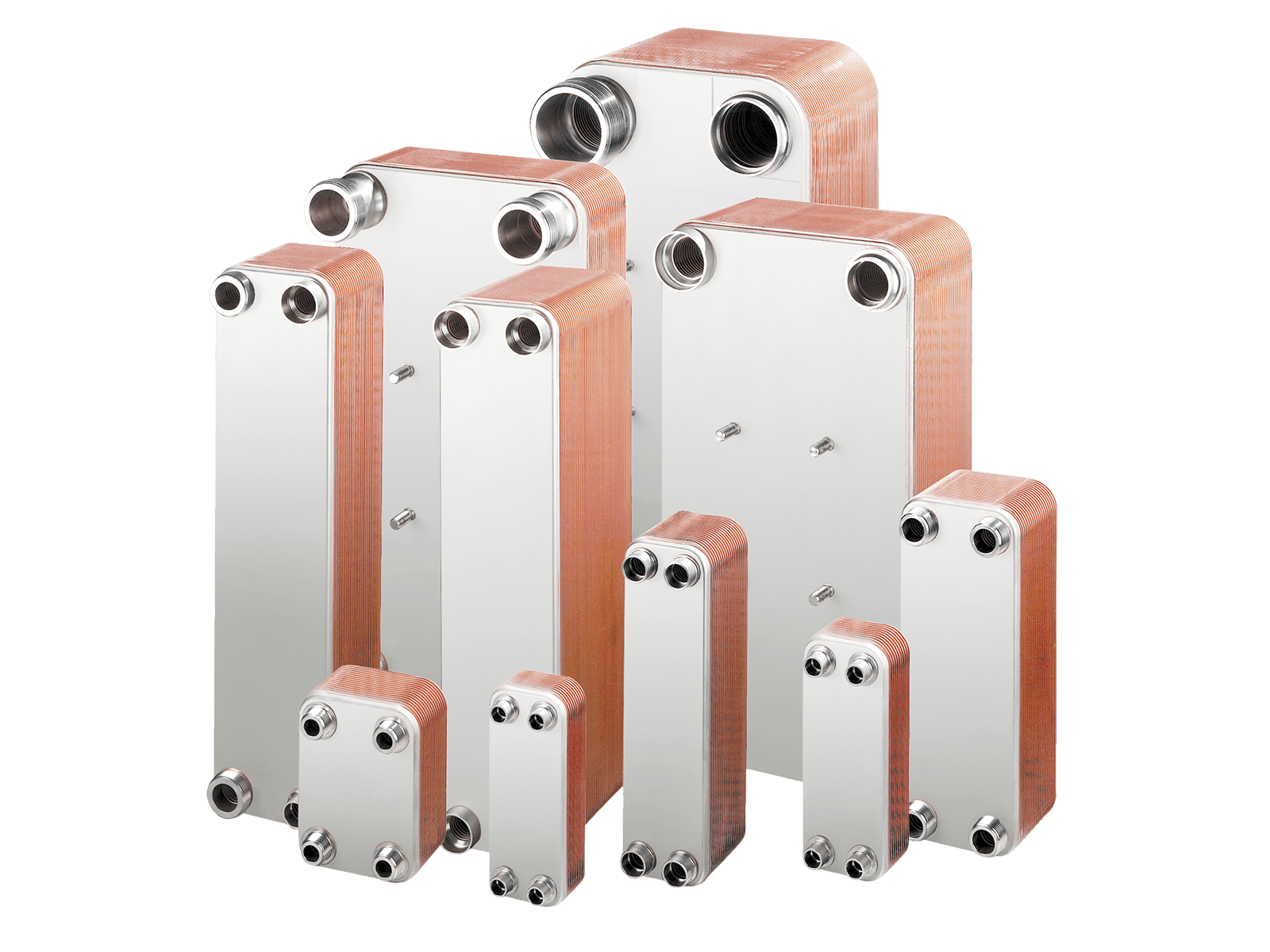
Plate heat exchangers can be brazed or gasketed.
|
|
|
|
Brazed plate heat exchangers |
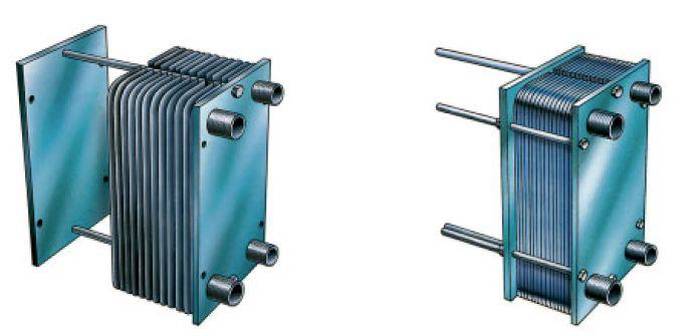
Gasketed plate heat exchangers with sealing gaskets |

A gasketed plate heat exchanger consists of a number of heat transfer plates, determined by the design parameters, which are mounted between the exchanger's carrying bars and held in place by the frame (fixed) plate and the pressure plate, forming a single assembly with them. All plates have gaskets, which ensure the tightness of the channels through which the working fluids flow.
The gasket system ensures that the media flow only through the channels intended for them, so that the fluids of the circuits flow continuously in opposite directions. The gasket design ensures that these fluids do not mix with each other.
The heat transfer plates have a corrugated (embossed) surface on both sides, which ensures turbulent flow of each fluid in the channels. The high turbulence of the fluid flow, together with a suitable ratio of medium volume to heat exchanger size, ensures a high heat transfer coefficient.
The same design principle is used in brazed heat exchangers. In this type of heat exchanger, however, special brazing technology is used to seal the medium channels instead of elastomer gaskets, achieving the same result.

Plate heat exchanger components
The main components of a plate heat exchanger are the heat transfer plates, the frame (fixed) plate and the pressure (movable) plate, the connecting elements and the carrying bars. The heat transfer plates are hung on the upper carrying bar and rest on the lower one. The carrying bars also serve to centre the heat transfer plates.
These plates are placed one after another between the frame plate and the pressure plate, forming a pack that is then tightened with bolts into a single monolithic unit.
Gaskets
Materials used:
|
Nitrile rubber |
General use, oil-resistant material |
|
EPDM |
General use, high temperatures |
|
Original "HeatSeal"™ material |
High temperatures, especially for steam heating |
Glue-free "Clip-on" sealing gaskets are fixed to the edge of the heat transfer plate with special clips.
Assembly
Manufacturers supply pre-assembled, pressure-tested heat exchangers.
Gasketed plate heat exchangers can easily be opened for inspection and cleaning.
If the capacity of a gasketed heat exchanger needs to be increased, this can be done quite simply by installing additional heat transfer plates.
The drawings show the assembly sequence of a gasketed plate heat exchanger.
|
|
|
|
1. The assembled heat exchanger frame. It consists of the frame and pressure plates, the upper and lower carrying bars and the end pieces. |
2. First, the end heat transfer plate is placed on the frame. |
|
|
|
|
3. Then the other plates are added according to the specification. |
4. Bolts are inserted into the frame and pressure plates; using a spanner (or another suitable tool), they tighten the plate pack (to the specification) into a single, sealed heat exchanger assembly. |

Installation
All brazed and gasketed plate heat exchangers have connections on the frame plate. For convenience, they are labelled, for example, S1, S2, S3 and S4.
A gasketed plate heat exchanger can stand directly on the floor at the place of manufacture. If possible, always secure it to the floor with fixing bolts for reliability. Remember that a plate heat exchanger takes up less space than traditional heat exchangers. When planning the installation of a plate heat exchanger, you only need to leave free space on one side of it. Pipe connections can be threaded or flanged, depending on the type of heat exchanger chosen.
Brazed plate heat exchangers

A brazed plate heat exchanger is small and light, cannot be dismantled and is inexpensive. This type of heat exchanger uses no gaskets; instead, brazing joins the plates into a single strong, sealed structure.
Brazed plate heat exchangers are especially suitable where the working pressure reaches 50 bar and the ambient temperature varies from -196 to +550 °C.
A brazed plate heat exchanger is usually installed in the pipework or mounted on a small bracket or stand.
The connection for the inlet of one medium is next to the connection for the outlet of the other medium. If S1 is the inlet of medium 1, then S4 will be the outlet of medium 2.
Each heat exchanger is supplied by the manufacturer with a manual describing the use of the connections for the inlet and outlet ports of each medium.
Depending on the pipe connection method chosen, prepare the pipe ends for threading, flange mounting or welding.
Alfa Laval supplies accessories for its plate heat exchangers, such as condensate drain trays and heat-insulating sheet materials.

Heat exchanger selection
To select a heat exchanger for a heat transfer task, certain parameters must be known. Knowing them, you can determine which heat exchanger is needed for the specific task. The six most important parameters are:
- The amount of heat to be transferred (thermal capacity);
- Inlet and outlet temperatures on the primary and secondary sides of the heat exchanger;
- The maximum permissible pressure drop in the primary and secondary circuits;
- Maximum operating temperature;
- Maximum operating pressure;
- Medium flow rate on the primary and secondary sides.
This article is based on Amegata.lt's hands-on experience. See it differently or have something to add? Write to us – we're happy to discuss, and if you share new, well-founded information, we will update the article. Updated October 2026.


